Articles
Heavy oil hydroconversion using an upflow reactor variant
Process/Project Optimization
L. PATRON, Contributing author, Milan, Italy
In heavy oil hydroconversion upflow reactors that use supported- or slurry-type catalysts, H2 or gas containing H2 is fed into the reactor’s bottom by means of bubbling. A fraction of this H2 diffuses from the gas into the reaction liquid through the gas bubbles-reaction liquid interface (hereafter referred to simply as the gas-liquid interface). The reaction liquid saturates free radicals, hydrogenates unsaturated structures and removes metals, sulfur and nitrogen; the H2 diffused within it remains incorporated in both organic and inorganic conversion products. The H2 incorporated in the products is always a small fraction of the total quantity of H2 fed to the reactor bottom. This proves that the hydrogenation capacity is limited by the H2-diffusion process, which is governed by the gas-liquid interface and not further expandable in a conventional upflow reactor. When the amount of H2 that diffuses into the reaction liquid is not sufficient to completely fuel the reactions that the hydroconversion process involves, the result is H2-deficient reaction liquid.
H2-deficient reaction liquid. In an upflow reactor with gas fed at the bottom by bubbling, the gas-liquid interface increases with the surface velocity of the gas until the bubble packing is completed. For reasons of geometry, in theory this happens when the gas holdup reaches a value of 0.299 in unit fraction;1 due to onset of the coalescence phenomenon, the gas-liquid interface gradually stops expanding beyond this point. Conventional upflow reactors of the type indicated at the beginning of this article typically use a gas holdup value not far from 0.3 at which the maximum value of the gas-liquid interface (m2/m3 of reactor volume) is reached.
Once the reactor operating pressure has been set, the hydroconversion is carried out with a fixed and not further expandable flow of H2 which diffuses into the reactions liquid. When the diffused H2 is insufficient to fuel all of the needed H2-consuming reactions, in particular the saturation of free radicals generated by molecular cracking, catalytic dehydrogenation of the reaction liquid results. This catalytic dehydrogenation makes the ratio of hydrogen to carbon (H/C ratio) in the heavy fraction of the reaction liquid lower than the H/C ratio of the same heavy fraction of the oil feed.
Dehydrogenation of the reaction liquid is consistently found in hydroconversion systems that use ebullated catalytic bed reactors (supported-type catalyst), as well as in hydroconversion systems using slurry bubble column rectors (slurry-type catalyst) with recycling of the unconverted residue. The lack of H2 results in the dehydrogenation of all the hydrocarbons that make up the reaction liquid, including asphaltenes. In turn, the dehydrogenation of the asphaltene fraction generates carbonaceous material (i.e., coke) that limits both the degree of conversion and the reactor’s hydroconversion capacity. Pseduo-polymerization of asphaltenes, if present, also generates carbonaceous residue.
Catalytic dehydrogenation of reaction liquid in heavy oil hydroconversion. Molybdenum, typically used as a catalyst in heavy oil hydroconversion, is a transition metal. In the relevant applications, molybdenum acts as molybdenite S = Mo = S and as HS-Mo-SH, the form of molybdenite coordinated with H2; this latter form acts as a hydrogenating agent as well as a radical scavenger. The saturation of free radicals (R*) generated by molecular cracking occurs by transfer of a hydrogen atom from HS-Mo-SH to the incomplete carbonic octet of R* (Eqs. 1 and 2):
HS-Mo-SH + R* → HS-Mo = S + RH (1)
S = Mo-SH + R* → S = Mo = S + RH (2)
HS-Mo-SH, the hydrogenated form of molybdenite, is restored by the H2 diffusing from the gas phase into the reaction liquid.
When the H2 consumption rate is higher than the weight flowrate of H2 diffusing into the reaction liquid, however, the hydroconversion catalyst (in the form S = Mo = S) activates the catalytic dehydrogenation of the hydrocarbons making up the reaction liquid itself. Eq. 3 is as follows:
S = Mo = S + > CH-CH < → HS-Mo-SH + > C = C < (3)
The hydroconversion catalyst can act as both a hydrogenating and a dehydrogenating agent in accordance with H2 availability. This holds true for any transition metal used as a catalyst, not only molybdenum.
Operating with H2 deficient reaction liquid. As dehydrogenation proceeds (either in the subsequent reaction stages or because of the recycling of unconverted residue), the H/C ratio of the asphaltene hydrocarbons becomes lower, making such hydrocarbons refractory to hydrogenation and insoluble in the reaction liquid and thus no longer convertible into distillates. These low H2-insoluble hydrocarbons (collectively known as carbonaceous residue) must be removed from the hydroconversion system. This may be accomplished through the final unconverted stream in hydroconversion systems devoid of recycling (typically using ebullated catalytic bed reactors) or in hydroconversion systems equipped with recycling (typically using slurry bubble column reactors), such as a purge stream. In the former case, the degree of conversion is limited to ~80%; in the latter, ~95%.
Operating with H2-deficient reaction liquid also limits the reactor’s hydroconversion capacity, which cannot increase without a corresponding reduction in the degree of conversion. While an increase in the reactor’s operating pressure would allow for increased availability of H2 in the reaction liquid, the increased cost for the plant makes increasing pressure an unattractive option.
Another way to avoid H2 deficiency is to lower the amount of H2 consumed by limiting molecular cracking. This can be accomplished by lowering the reactor temperature until the H/C ratio of the heavy fraction of the reaction liquid is not lower than the H/C ratio of the same heavy fraction of heavy oil feed. This would involve severely derating the system’s hydroconversion capacity, however, and increasing reactor pressure is not an economically sustainable option.
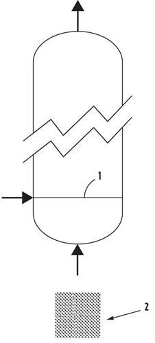
Expansion of gas-liquid interface as a countermeasure to avoid H2 deficiency. To overcome H2 deficiency without raising operating costs or reducing hydroconversion capacity, the flowrate of H2 diffusing into the reaction liquid must be increased by expanding the gas-liquid interface. This is achievable using a variant of an upflow reactor2 equipped with a means of H2 distribution with a high density of orifices per m2 of the horizontal reactor section (FIG. 1). These reactors are capable of creating a fluid dynamic regime wherein the specific surface of the gas-liquid interface (m2 of gas bubble surface per m3 of liquid) increases with the squared power of the gas holdup value, bringing hydrogenation capacity (per unit volume of reactor) up to values more than double what is seen in conventional upflow reactors. In hydroconversion systems using ebullated catalytic bed reactors, a fluid dynamic regime with an expandable gas-liquid interface is created in correspondence with the catalytic bed, above the distributor plate; in hydroconversion systems using slurry bubble column reactors, a fluid dynamic regime of this kind is preferably created over the entire height of the reactor.
 FIG. 1. Upflow reactor equipped with H2 distribution means (1) in the form of high orifice density (2).
When using a hydroconversion system equipped with a distillation unit for high boiler extraction and recycling of unconverted residue, the lack of H2 in the reaction liquid can be mitigated by maximizing the production of middle distillates at the expense of H2-rich gases and light hydrocarbons.3
Achievable results. An increase in hydrogenation capacity brought about by expanding the gas-liquid interface can strongly expand the capacity of a hydroconversion system and extend the lifetime of its catalyst. In systems that utilize ebullated catalytic bed reactors, the reduction of dehydrogenation of the reaction liquid to zero will result in an unconverted stream that is completely recyclable to the reactor, thus allowing the completion of hydroconversion with reaction stages in series or preferably in parallel for easier product extraction. The reduction of carbonaceous residue associated with dehydrogenation will proportionally extend the useful life of the supported-type catalyst. In systems using slurry bubble column reactors, the reduction or elimination of carbonaceous residue production (which is typically removed by a purge stream) greatly decreases the consumption of slurry-type catalyst.
LITERATURE CITED
1. Shaikh, J. and M. Al-Dahhan, “A review on flow regime transition in bubble columns,” International Journal of Chemical Reactor Engineering, Volume 5, 2007.
2. International patent, application number PCT/IT2021/050122: “Hydrotreatment upflow reactors with high hydrogen-hydrocarbon liquid contact surface and improved hydrogenation capacity.”
3. U.S. patent, application number 16952824: “Process for the hydroconversion of heavy hydrocarbon oils with reduced hydrogen consumption.”
LUIGI PATRON served as Chairman and CEO of the engineering company Snamprogetti between 1997 and 2005. Snamprogetti, formerly a subsidiary of ENI and later merged with Saipem, designed and built the demonstration unit used to validate the first commercially applied heavy oil slurry hydroconversion technology. Mr. Patron
has since continued working on hydroconversion technologies independently.

